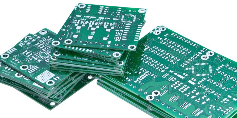
A PCB layout designing is critical because the wiring quality influences the performance of the system. The layout developed must be efficient, reliable, cost-effective, and still perform as required. Unlike the past years, the modern PCB boards are compact, complex, and lightweight; hence so much work is put into knowing the correct layout design. Several aspects must be considered for the PCB layout to develop a design that’s fit for the real world. We expound on the steps for designing a PCB layout below.
Steps for Designing a PCB Layout
PCB layout design has a significant role in the entire development process. Below are the six steps contained in the design process.
1. Determining the Concept
The process begins with the concept, but after knowing why you need a PCB. The concept involves identifying what the PCB is supposed to do, its qualities, and how it will be connected with other devices and circuits.
Still, in this first stage, the electrical engineer determines its placement on the end product and approximates its size and dimensions. PCBs are used in many applications in different environments with varying temperatures. Consider the maximum range of temperature the PCB can reach and the settings it can be used in and still function correctly.
2. Schematic Drawing
This step draws its idea from the concept phase. The circuit diagram is drawn to a smaller scale and consists of the names, ratings, and values of all the components connected to it. Any additional information related to how the electrical components operate is also included. Since all device names are now known, the material bill is developed in the process, and you can tell approximately how much money is needed to facilitate the design process. The documents are constantly updated in case any changes come up.
3. Board-Level Block Diagram
It is a drawing to show the final size of the PCB, with the exact measurements to be used by the electronic engineer. Divide the board into sections and put a mark where each block will be placed. In addition, Designate the components into sections based on their connectivity and similarity for short and more straightforward tracing.
4. Placing of Components
The fourth step is to determine the positioning of each component in the board. Component placement may not occur immediately because the chances of refining may be high until the designer gets a perfect position.
5. Routing
Routing is closely related to the placement step. Wires are added to the board to connect all components and form a complete circuit. In the process, all Integrated Circuit design rules are followed for proper functioning.
6. Testing
Product testing is the final step of the PCB layout design process. It determines how viable a product is and if it qualifies for use or needs to be worked on again. Conduct several tests to see if it meets all your requirements. If not, recommend the necessary adjustments required for it to operate as desired.
Conclusion
Proper PCB layout design prevents electrical problems like interference and promotes good signals. You should follow the step-by-step guide as it is for excellent results and ease of identifying any errors.
